Wanted a more depth and ambient experience in gaming and watching movies. Here is how I created a DIY backlight based on the LS100 from Corsair. The backlight can be used for ambient lighting and screen mirroring. It also syncs with all corsair products and custom lighting effects can easily be added in iCUE.
This project requires you to have some experience with electronics, soldering and Arduino programming.
Background: Corsair released the LS100 in November 2019 and I decided to create an ambient backlight with an Arduino using the capabilities of a LS100.
This project uses the iCUE software from Corsair so it only works on Windows computers that can run iCUE. The ambient backlight does not work with regular TV. The LED controller uses SATA power and should me mounted inside a PC case and only works if the PC is running.
First let’s start with the parts that are required for the project.
Required components: (~25€)
- compatible Arduino board, see CLP library Requirements
- Individually addressable RGB LED strip (60 LEDs/m)
- small PCB for the LED controller
- wires for the LED controller
- long cables for power supply to the LED strip
- SATA power extension cable
- 2x 3-pin header and connector
- small case for the LED controller
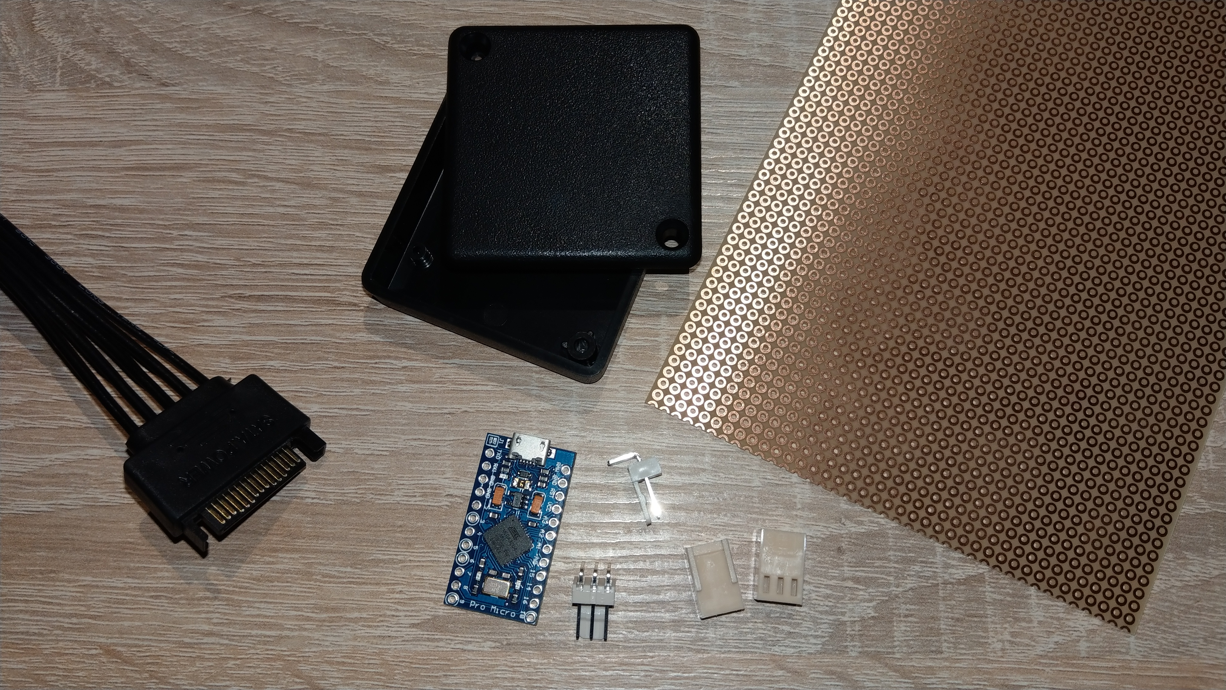
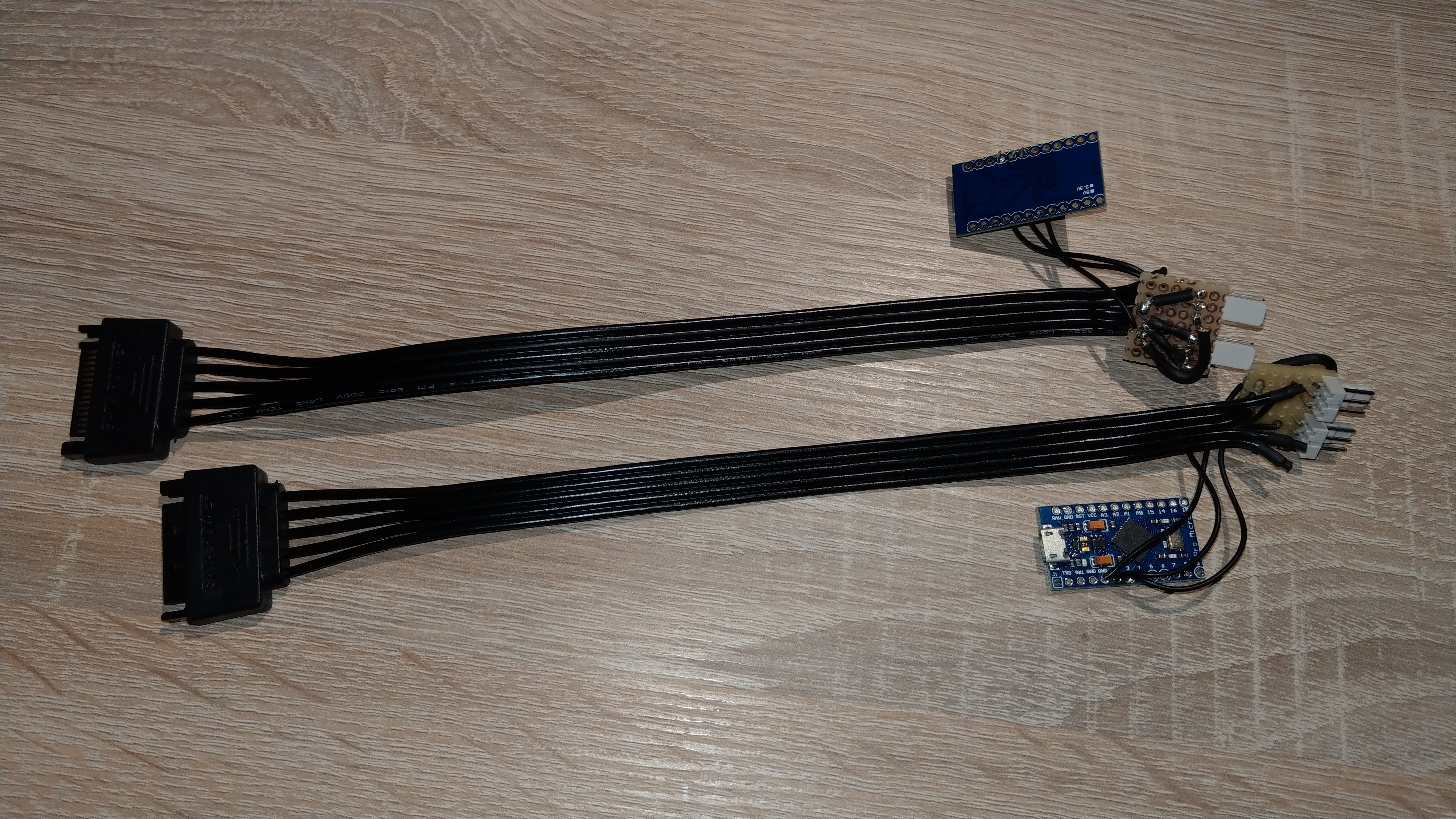
I used a SparkFun Pro Micro - 5V/16MHz and 84 LEDs of a WS2812B 60 LEDs/m strip. As connectors I used 3-pin fan connectors from reichelt.com (PSK 254/3W, PSS 254/3W, PSK-KONTAKTE, CRIMPZANGE PSK). But it is also possible to use jst-sm 3 pin connectors as they are used on most LED strips. The black universal case is 50x50x15mm. I created two LED controllers that you can see on some pictures, but you only need one for one monitor.
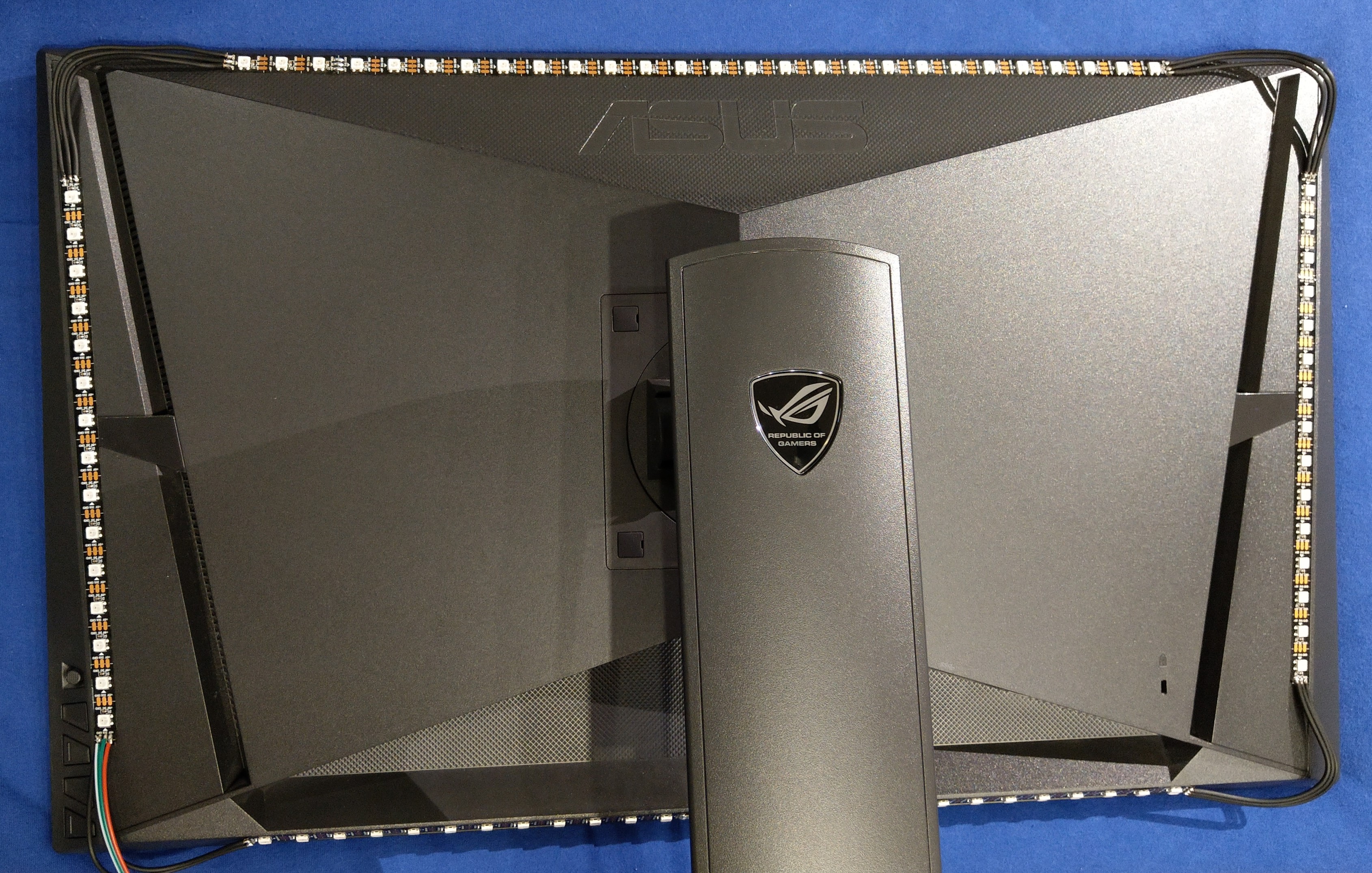
Step 1 Cut the RGB LED Strip to Fit Your Monitor
Look at the back of your monitor to see how and where you can place the LED strip pieces. Cut the LED strip into four pieces, two pieces for left and right and two for the top and the bottom of the monitor. Keep in mind the direction of the LED strip indicated by small arrows on the strip. Either the left or the right strip piece is connected to the LED controller and the direction must be upwards. This means looking at the back of the monitor and connecting the left strip piece to the LED controller (as shown in the picture) the signals go clockwise. If the right strip piece is connected to the LED controller the signals go counter clockwise.
I cut the RGB LED strip into pieces with 27 LEDs and 15 LEDs. The iCUE Software is limited to 27x15 LEDs so it’s a good choice to use this for the pieces. If you have a bigger monitor you can use more LEDs but have to adopted the Arduino sketch in step 4.
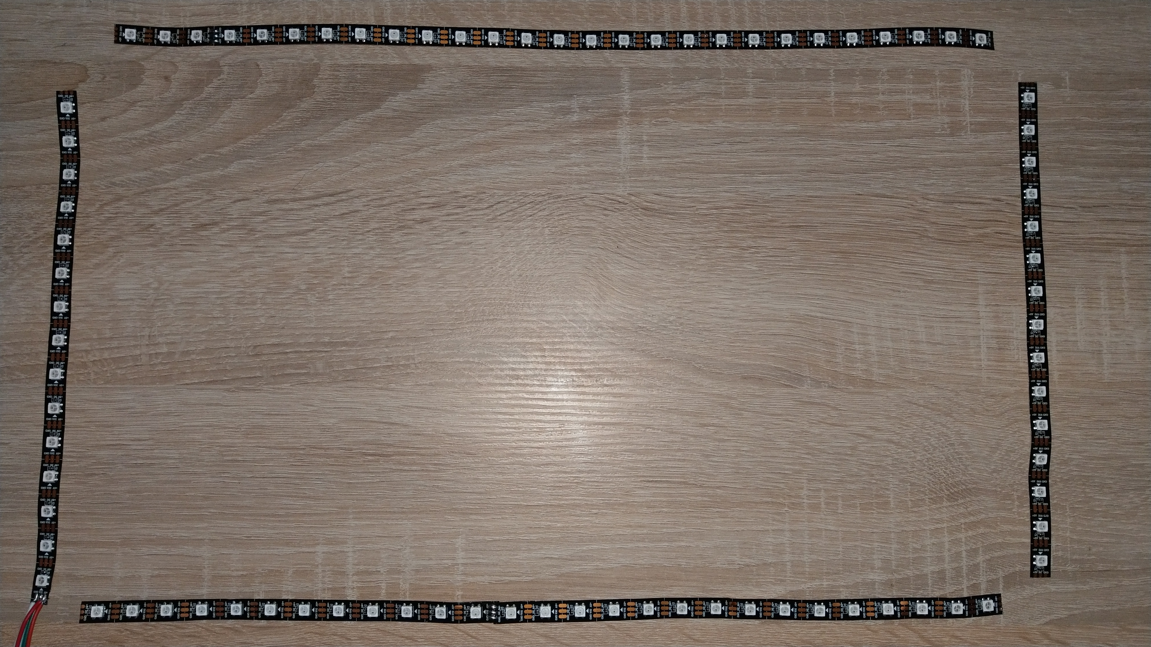
Step 2 Solder the LED Strip Pieces
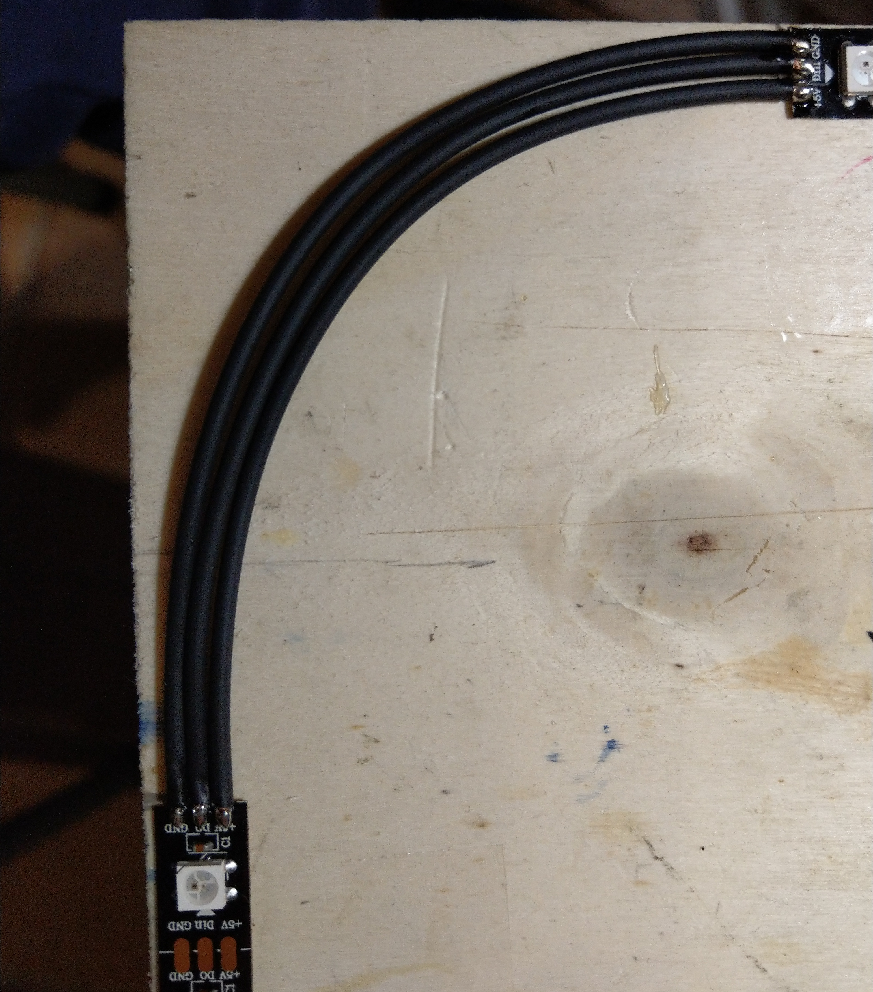
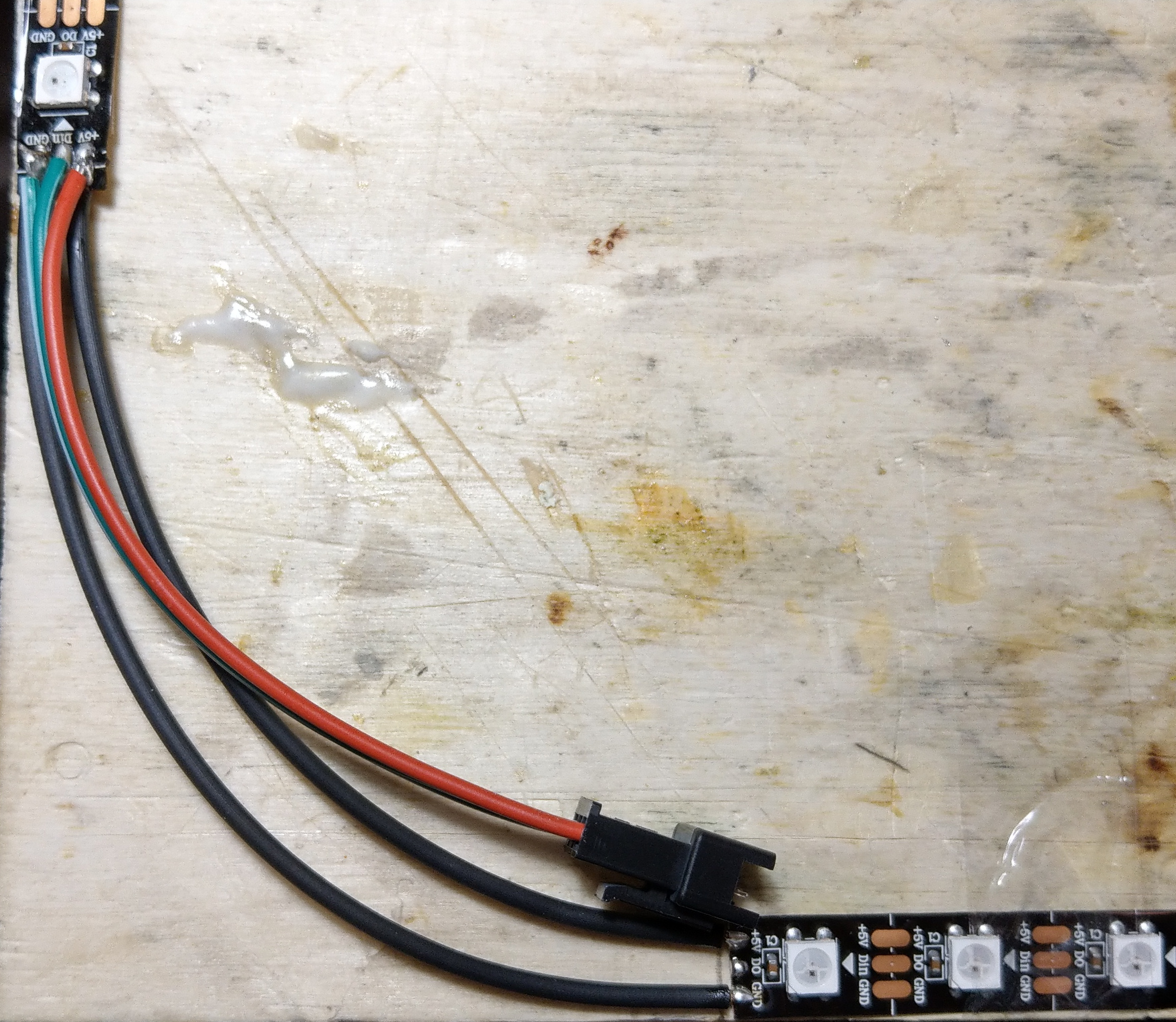
Connect all ends of the LED strip pieces expect the signal of the first and the last strip. Use cables that can handle the current for powering the LEDs and are long enough so you can mount them to you monitor.
To make the soldering easier I taped the LED strip pieces on a piece of plywood that has the size of my monitor. I first added some solder on the LED strip pads and the soldered the cables. Solder a jst-sm 3 pin connector to the beginning of the strip to later connect it to the LED controller. After soldering I used a multimeter to check all connection.
Step 3 Mounting the LED Strip Onto Your Monitor
Most LED strips have self-adhesive tape else add self-adhesive tape to mount the strip to your monitor.
Step 4 Program the Arduino
Install the “Corsair Lighting Protocol” and the “FastLED” library using the Library-Manager in Arduino IDE via Tools->Manage Libraries…. Install the CLP Boards. Open the “AmbientBacklight” example in the Arduino IDE via the File menu->Examples->Corsair Lighting Protocol->AmbientBacklight. Select the Arduino Board type in the Tools->Board menu. You must select the board with “CLP” at the beginning. In my case I selected “CLP SparkFun Pro Micro 5V, 16 MHz”. Select Tools->Device->Smart Lighting Controller. Last but not least select the COM Port of your Arduino and upload the sketch.
Step 5 Create the LED Controller
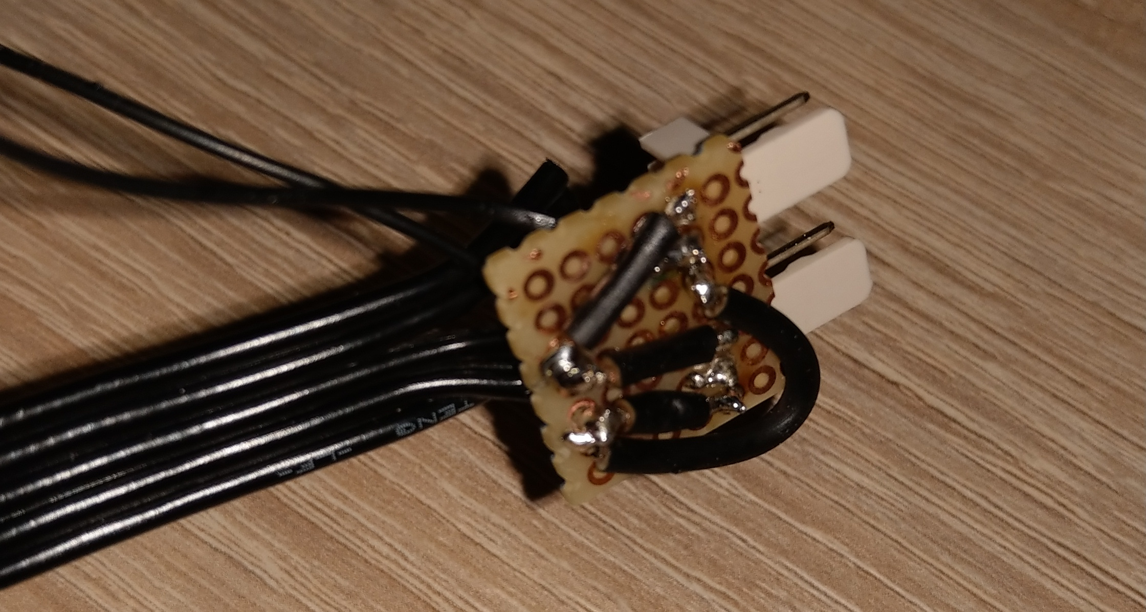
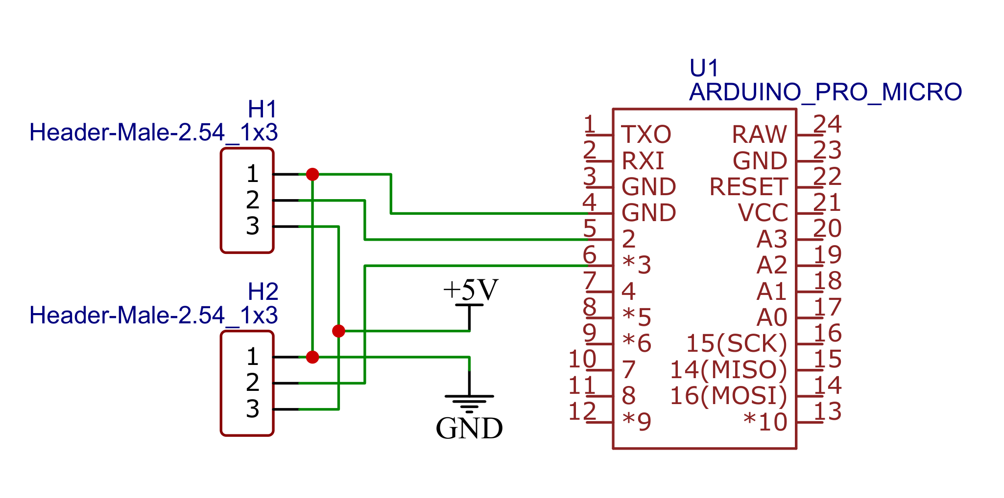
Cut the SATA power extension cable in half and use the side with the contact pins as you can see in the picture below. Cut out a small piece of PCB, so you can fit the 3-pin headers and the SATA power cables on it. Solder the 3-pin header onto the pcb. I used diamond needle files to make the holes of the PCB bigger for the two cables of the SATA power cable (GND and 5V). The SATA power cable consists of five cables the one in the middle is the 5V lane and the two cables next to it are the GND lanes. Solder the 5V and one GND cable to the PCB. Solder connections from the GND and 5V lanes to the left and right pins of the 3-pin headers. Depending on how you want to do the polarity you must check that it matches with the polarity of the RGB strip connector.
Now solder small wires to the middle pin (signal) of the 3-pin headers and connect them to the pin 2 and 3 of the Arduino. You must remember which pin header you connect to which Arduino pin. Solder a wire from the GND lane of the SATA power cable to a GND pin of the Arduino.
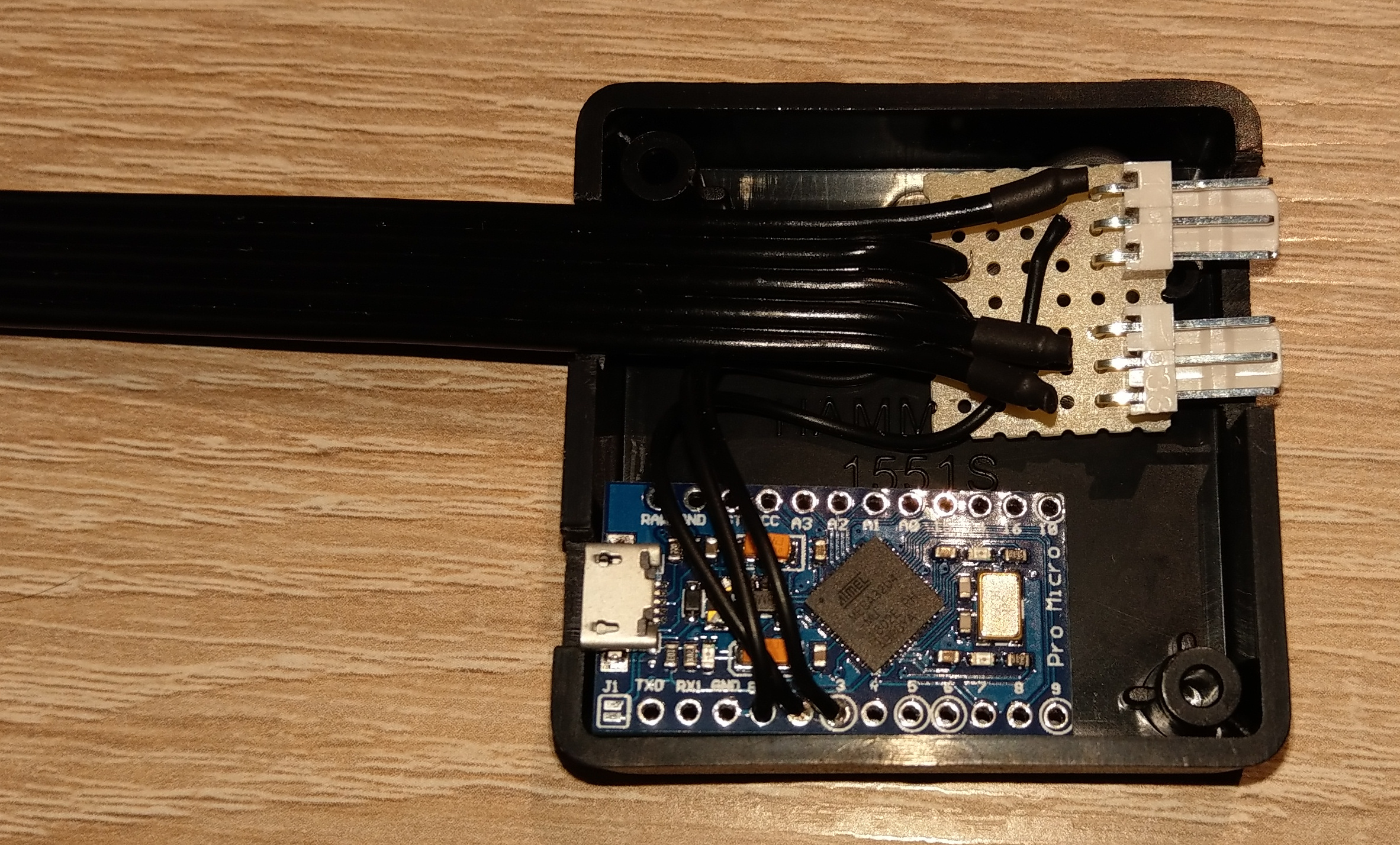
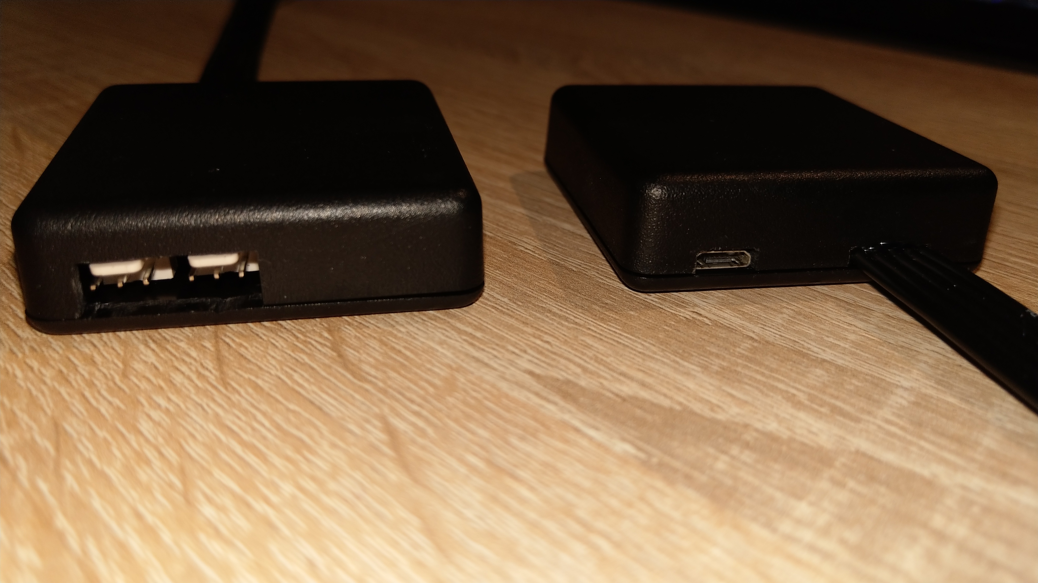
Cut holes into the case for the USB, SATA power and 3-pin headers using a fretsaw. Check that all connectors are accessible when the case is closed. I used hot glue to glue all the components onto one side of the case and then screwed the two sides of the case together.
Step 6 Connect the LED Controller, Monitor and Computer
Connect the RGB LED strip from the back of your monitor to the connector which is connected to pin 2 of the LED controller. I created an adapter cable for the LED strip JST connector to the LED controller 3 pin header. Connect the LED controller to a USB port of your PC. Connect the LED controller to a SATA power connector of the PC PSU.
Step 7 Configure the Ambient Backlight in iCUE
Install iCUE if it is not yet installed. Open iCUE and select the LS100 STARTER KIT. Select “LIGHTING SETUP” and configure “Single Monitor Mode” for the Lighting Channel 2. The channels in iCUE are swapped, so channel 1 of the LED controller is channel 2 in iCUE. Now select the channel on the left and add a new lighting effect. In the drop down menu select “VIDEO LIGHTING”. If you not familiar with iCUE you can watch videos on YouTube on how to setup LS100 in iCUE.
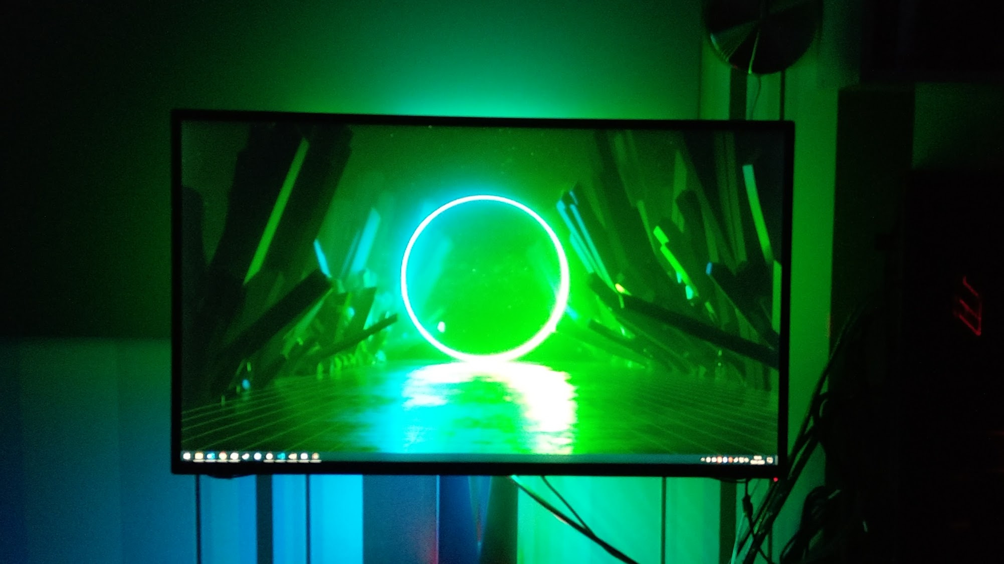
Now you can enjoy your DIY ambient backlight.
If you have any comments, feedback or questions use GitHub or Discord.